

『Fire Pump Flow Meter Test Procedure: Step-by-Step GPM Verification and Pump Curve Tracking』Related information(flow rotameter|digital flow meter|balo meter|hydraulic flow meter|volumetric meter|positive displacement meter|pitot tube flow meter|displacement meter|cfm meter|variable area flow meter|inline flow meter|differential pressure flow meter|calibrated flow meter|velocity meter|paddle wheel flow meter|oval gear flow meter|anemometer hvac|multiphase flow meter|doppler flow meter|thorpe tube flowmeter|heat flow meter)
Fire Pump Flow Meter Test Procedure: Step-by-Step GPM Verification and Pump Curve Tracking
Quick Answer: Install a calibrated flow meter on the discharge test header or bypass loop. Record GPM, suction pressure, discharge pressure, pump speed, and power at zero flow, rated flow, and 150 percent flow. Correct the points for speed and compare them with the factory pump curve. A deviation above 5 percent usually means wear, blockage, air leakage, or a meter installation problem.
Why a Flow Meter Matters in This Test
Fire pump acceptance tests and annual tests follow NFPA 20 and NFPA 25 requirements. The test proves that the pump still delivers the rated flow at the rated pressure. Without a reliable flow meter you only have pressure readings. Pressure alone cannot confirm GPM. A fire pump can show acceptable discharge pressure and still fail the required flow. We have seen this on customer sites in Southeast Asia and the Middle East.
For a 1000 GPM fire pump the test points are typically zero flow, 1000 GPM rated flow, and 1500 GPM. The flow meter becomes the primary reference for GPM verification and pump curve tracking.
Equipment You Need
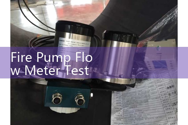
Use a calibrated flow meter with a valid certificate. The meter should cover the expected pipe velocity range. You also need two pressure gauges, one on the suction side and one on the discharge side. Add a tachometer or use the pump controller speed signal. A clamp meter records motor current and voltage. A data logger or paperless recorder helps capture a stable curve.
Silver Instruments supplies electromagnetic flow meters and clamp-on ultrasonic flow meters for this job. For permanent test headers a DN150 electromagnetic flow meter is common. For temporary field checks a clamp-on ultrasonic meter avoids pipe cutting and shutdown.
Step 1: Check Meter Installation and Straight Run
Install the flow meter on the discharge test line or the bypass loop. For an electromagnetic flow meter keep at least 5D upstream and 2D downstream straight run wherever possible. For a clamp-on ultrasonic flow meter keep 10D upstream and 5D downstream. The pipe must be full of water during the test. Air bubbles cause large errors in GPM verification.
Clean the pipe surface before mounting clamp-on transducers. Use coupling compound evenly. Do not place the sensors on the top or bottom of a horizontal pipe. The top collects air and the bottom collects sediment. Place them on the side at a 3 o clock or 9 o clock position where possible.
Step 2: Run the Zero Flow Point
Start the fire pump and close the discharge valve. Let the pump run for a short time while monitoring casing temperature. Record the suction pressure and discharge pressure. Flow is zero. This point gives the shutoff head. Compare it with the factory curve at the same speed. If the shutoff head is low by more than 5 percent, check for wear ring clearance, impeller wear, or air leakage.
Step 3: Run the Rated Flow Point
Open the discharge valve slowly until the flow meter reads the rated GPM. For a 500 GPM pump hold 500 GPM. For a 1000 GPM pump hold 1000 GPM. Wait for the reading to stabilize. Record flow rate, discharge pressure, suction pressure, pump speed, voltage, and current. Calculate total head in feet using this formula: head feet equals discharge psi minus suction psi multiplied by 2.31. In metric units: head meters equals discharge kPa minus suction kPa divided by 9.81.
Step 4: Run the 150 Percent Flow Point
Open the discharge valve further until the flow meter reads 150 percent of rated flow. On a 750 GPM pump this is 1125 GPM. On a 1500 GPM pump this is 2250 GPM. At this condition the fire pump operates beyond its normal range. Discharge pressure drops. Flow measurement stability matters here because high velocity and possible air entrainment cause fluctuation. Use damping or averaging in the flow meter if available.
Record the same variables as the rated point. Keep the total test time reasonable to avoid heating the water and the pump. For diesel fire pumps check engine temperature and oil pressure during the 150 percent point.
Step 5: Speed Correct and Plot the Pump Curve
Pump curve tracking only works when all points align to the same rated speed. Electric and diesel drivers rarely hold exact rated RPM under loa
Plot zero flow, rated flow, and 150 percent flow. Draw the test curve through the three points. A healthy pump follows the factory curve shape with small scatter. The measured points should stay within the acceptance tolerance stated in the job specification or NFPA 20. In practice many sites allow plus or minus 5 percent on GPM verification.
Step 6: Compare and Decide
If the test points fall below the factory curve at rated flow and 150 percent flow, the pump needs inspection. Look for clogged suction strainer, partially closed valve, wear ring damage, impeller erosion, or wrong rotation. If the curve is above the factory curve at shutoff, check for a tachometer error or a closed valve creating false head.
Do not adjust the flow meter to force a passing result. That changes the pump curve tracking data and hides a real fire protection problem. Instead verify the meter with a bucket test or another calibrated meter.
Common Field Issues We See
Most errors in fire pump flow meter testing come from installation, not the meter itself. Air pockets collect at high points. Clamp-on ultrasonic transducers lose signal on old painted pipe. Electromagnetic flow meters show unstable readings when grounding is poor. In one installation in Indonesia a DN200 electromagnetic meter on a test skid gave bad GPM data because the liner was damaged during welding. The meter was installed before the flange was welded and the heat damaged the PTFE liner. Always weld the flanges first, then install the meter body.
Meter Selection for Fire Pump GPM Verification
For permanent test skids and discharge headers choose the Silver SFE-E electromagnetic flow meter. Common sizes for fire pumps are DN80, DN100, DN150, and DN200. Accuracy is plus or minus 0.5 percent of reading. Output options include 4-20 mA HART and RS485 Modbus RTU. The meter has a PTFE liner and 316L electrodes as standard. It handles conductive water, seawater, and foam concentrate after calibration.
For temporary field tests choose the Silver SUL-C clamp-on ultrasonic flow meter. It fits DN25 to DN3000 pipe without cutting. Accuracy is plus or minus 1.0 percent of reading. The data logger stores flow rate over time which helps pump curve tracking. Output includes 4-20 mA and Modbus. This meter works well for fire pump service teams that test at different sites every week.
FAQ: Fire Pump Flow Meter Test Procedure
What accuracy is required for fire pump GPM verification? A flow meter with plus or minus 1.0 percent of reading or better is preferred. Many industrial electromagnetic meters meet plus or minus 0.5 percent. Portable clamp-on meters often meet plus or minus 1.0 percent.
Can I use a clamp-on ultrasonic flow meter for fire pump testing? Yes if the pipe is full, clean, and within the meter transducer range. Clamp-on meters save time because you do not cut the pipe. Use proper transducer spacing and avoid air pockets.
Which test points are required for pump curve tracking? Record zero flow, 100 percent rated flow, and 150 percent rated flow. At each point record GPM, suction pressure, discharge pressure, pump speed, and power. Correct all points to rated speed before plotting.
How often should a fire pump flow meter test be done? NFPA 25 requires annual flow testing for many fire pump installations. Local regulations may require more frequent tests. A permanent flow meter on the test header makes monthly or quarterly checks faster.
What causes a fire pump to fail a flow test? Common causes include worn wear rings, impeller damage, clogged suction strainer, air leaks, wrong rotation, or a partially closed valve. A reliable flow meter separates hydraulic problems from gauge errors.
Need a flow meter for fire pump GPM verification? Send us your pipe size (DN), flow range in GPM or m3/h, pressure rating, and fluid type. Silver Automation Instruments will provide a product selection and price. Tel: +86-25-68650347. WhatsApp: +86-25-52155837. WeChat: +86 15365082610.
 Hot Blog
 Related AD